• einbauhinweise_1046x850.jpg

Installation instructions for ultrasonic sensors

Notes for installation and operation

Ultrasonic sensors can be incorporated and operated in any position. However, positions which could lead to severe soiling of the sensor surfaces should be avoided. Drops of water and severe deposits on the surface of the transducer can impair the function. However, small dust deposits and splashes of paint do not affect the function.
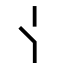
For scanning objects with flat and smooth surfaces, the sensors should be mounted at an angle of 90 ± 3° to the surface.
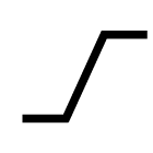
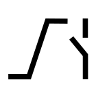
On the other hand, rough surfaces can cope with much larger angular deviations. In terms of ultrasonics, a surface is considered rough when its peak-to-valley height is in the order of magnitude of the wavelength of the ultrasonic frequency or is larger than this.
The sound is then reflected in a scattered fashion and this can lead to a shortening of the operating range. In the case of rough surfaces the maximum permissible angular deviation and the maximum possible detection range should be determined by way of trials.
Sound-absorbent materials, e.g. cotton wool or soft foams, can reduce the operating range. On the other hand, liquids and solid materials are very good reflectors of sound.

Mounting spacing and synchronisation

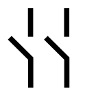
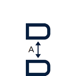
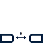
If two or more sensors are mounted too close to one another, they can influence one another. To avoid this, either the mounting spacing must be sufficiently large, or the sensors must be synchronised with one another. The following table lists the minimum mounting distances between unsynchronised sensors.

Minimum mounting distances between unsynchronised sensors

Operating range
0.07 m ≥ 0.25 m ≥ 1.10 m
0.15 m ≥ 0.25 m ≥ 1.30 m
0.24 m ≥ 0.25 m ≥ 1.40 m
0.25 m ≥ 0.35 m ≥ 2.50 m
0.35 m ≥ 0.40 m ≥ 2.50 m
0.7 m ≥ 0.70 m ≥ 4.00 m
1.0 m ≥ 0.70 m ≥ 4.00 m
1.3 m ≥ 1.10 m ≥ 8.00 m
3.4 m ≥ 2.00 m ≥ 18.00 m
6.0 m ≥ 4.00 m ≥ 30.00 m

The mounting distances should be regarded as standard values. In the case of objects positioned at an angle, the sound can also be "reflected" to an adjacent sensor. Minimum mounting distances should then be determined by way of trials.
Some sensors can be synchronised with each other and this enables much smaller mounting distances to be used than those given in the table. Please refer to the descriptions of the various sensors.

If sensors are mounted at distances from one other that are less than the values specified in the table, the ultrasonic sensors must be synchronised with one another. This means that the sensors always carry out their measurements at the same time.

Synchronisation using pin 5
Many microsonic sensors have integrated synchronisation, which can be activated for example simply by connecting to Pin 5 on the device connector. Other sensors require an external clock signal.

Redirecting the sound

The sonic beam can be redirected via a reverberant, smooth reflecting surface without significant losses. Accessories are available to deflect the sound through 90° .
These can be used to advantage in certain confined installations.

90°- beam deflector

Accuracy

The (absolute) accuracy is the discrepancy between the real distance between sensor and object and the distance as measured by the sensor. The accuracy obtainable depends on the reflective properties of the object and the physical influences affecting the velocity of sound in air.
Objects with poor reflective properties or a surface roughness greater than the wavelength of the ultrasonic frequency have an adverse effect on the accuracy achievable. It is not possible to quantify this exactly but as a rule of thumb we can assume an inaccuracy of several wavelengths of the ultrasonic frequency employed.

Air temperature

The biggest influence on the velocity of sound and hence on the accuracy is the temperature of the air (0.17%/K). Therefore, the majority of ultrasonic sensors from microsonic contain temperature compensation circuitry. Even better is to carry out a comparative measurement over a known distance to determine the influence of temperature. The pico column sensor is, for example, designed for such comparative measurements. With temperature-compensated sensors, an accuracy of ≤ ±1 % can be achieved.

Air pressure

The velocity of sound over a wide range does not depend on the pressure of the air. microsonic has special sensors for measuring distances in up to 6 bar overpressure.

Relative humidity

In comparison to the influence of temperature, the effect of the humidity of the air on the accuracy can be ignored.

Repeat accuracy R

The repeat accuracy, or reproducibility, describes the deviation in the measured distances under the same conditions over a defined period.
The repeat accuracy of microsonic sensors is better than ±0.15%.

Top