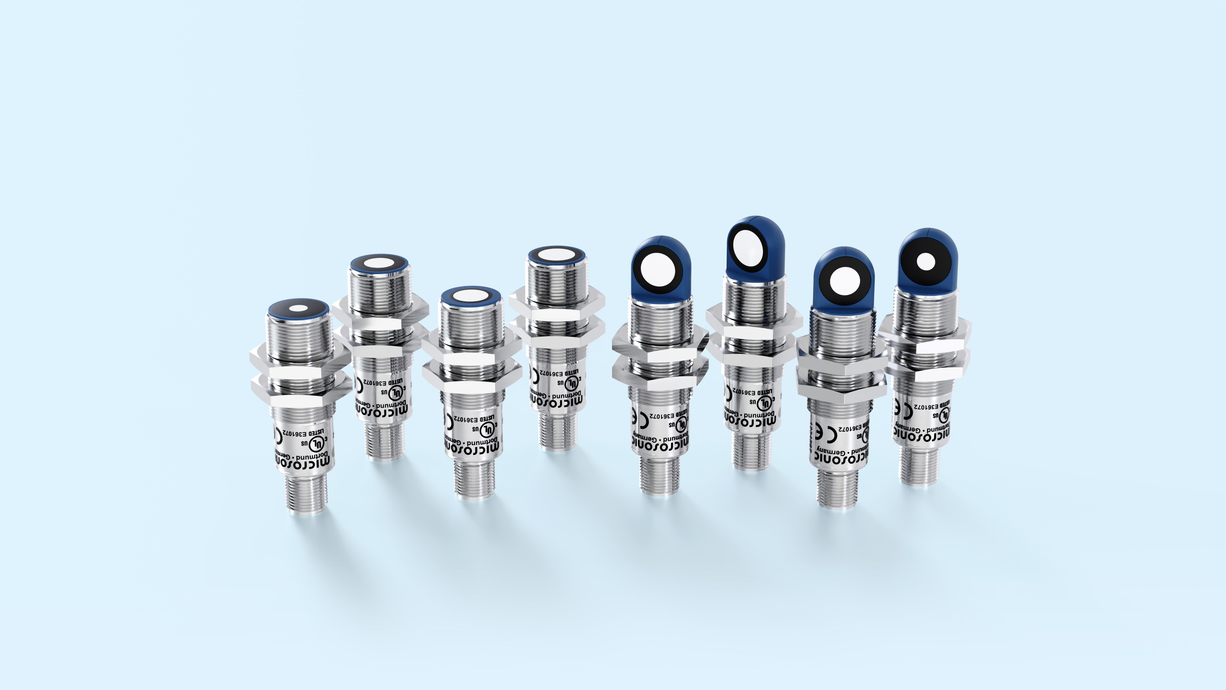








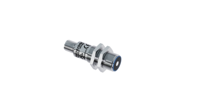
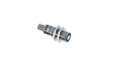
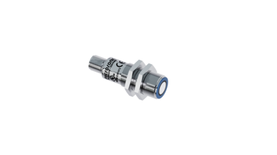
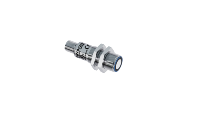
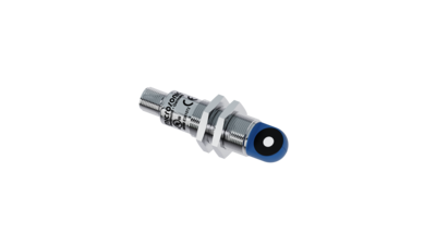
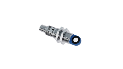
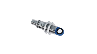
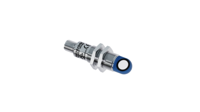

Auf dem Foto sind die lpc+ Ultraschall-Abstandssensoren in den vier verschiedenen Tastweiten zu sehen.

lpc+

lpc+ well equipped: 2 Push-Pull switching outputs or 1 Push-Pull switching output with an analogue output in M18 housing.

검출 영역
  • Symbolische Darstellung eines Ultraschallsensor mit einer Tastweite von 0,15 m.0.15 m
  • Symbolische Darstellung eines Ultraschallsensor mit einer Tastweite von 0,25 m.0.25 m
  • Symbolische Darstellung eines Ultraschallsensor mit einer Tastweite von 0,35 m.0.35 m
  • Symbolische Darstellung eines Ultraschallsensor mit einer Tastweite von 1,0 m.1.0 m
하우징 규격
  • Symbolische Darstellung 1 Analogausgang mit einem zusätzlichen pnp-Schaltausgang mit IO-Link-Schnittstelle
  • Symbolische Darstellung 2 Schaltausgänge mit IO-Link-Schnittstelle
출력

하이라이트

  • Analogue output 4–20 mA or 0–10 V plus 1 Push-Pull switching output in M18 design
  • IO-Link interfacefor support of the new industry standard 
  • Smart Sensor Profiles more transparency between IO-Link Devices
  • Improved temperature compensation adjustment to working conditions within 120 seconds
  • 캐나다 및 미국 안전 표준에 대한 UL 인증

Basics

  • 2 Push-Pull switching outputs pnp or npn basis
  • 4 detection ranges with a measurement range of 20 mm to 1.3 m
  • microsonic Teach-in on pin 5
  • 0.1 mm resolution
  • 10~30V 작동 전압
  • 링크컨트롤(LinkControl)PC로 센서를 환경설정

Sensormatrix

The sensor matrix gives an overview of standard sensors from lpc+ family. Make your choice based on operating range and available outputs and click in the matrix.

The lpc+ ultrasonic sensors

are optionally equipped with two Push-Pull switching outputs or an analogue output plus a Push-Pull switching output. The compact series with M18 threaded sleeves coves four detection ranges from 20 mm to 1.3 m.

Ultrasonic sensors with the Push-Pull output stage support SIO and IO-Link modes. Sensors with analogue output are optionally available with 4–20 mA current output or 0–10 V voltage output.In SIO mode, sensors are configured using the microsonic Teach-in procedure on pin 5.
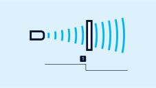
 

two output stages:

2 output stages and 4 detection ranges available:

Symbolische Darstellung 2 Schaltausgänge mit IO-Link-Schnittstelle2 Push-Pull-switching outputs, optionally in pnp or npn circuitry with IO-Link interface
Symbolische Darstellung 1 Analogausgang mit einem zusätzlichen pnp-Schaltausgang mit IO-Link-Schnittstelle1 Push-Pull switching output and analogue output 4–20 mA or 0–10 V

스위칭 출력이 있는 큐브 센서에는 세 가지 작동 모드가 있습니다.

  • 단일 스위칭 포인트
  • 양방향 반사 장벽
  • 윈도우 모드
Teach-in of a switching point
스위칭 포인트의 티치-인
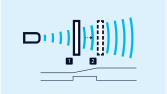
Teach-in Zweiweg-Reflexionsschranke Ultraschallsensor
2방향 반사 장벽의 티치-인

고정 장착된 반사경이 있는 2방향 반사 장벽의 티치-인

  • 버튼 T2를 약 3초간 누릅니다.
  • 그런 다음 버튼 T2를 다시 약 10초간 누릅니다.

창 구성

단일 스위칭 출력에 두 개의 스위칭 포인트가 있는 경우, 절차는 아날로그 특성을 설정하는 것과 동일합니다.

아날로그 측정영역 또는 검출영역 내 2 개의 스위 칭 포인트의 티치-인

NCC/NOC

상승/하강 아날로그 특성도 버튼을 통해 설정할 수 있습니다.

LinkControl

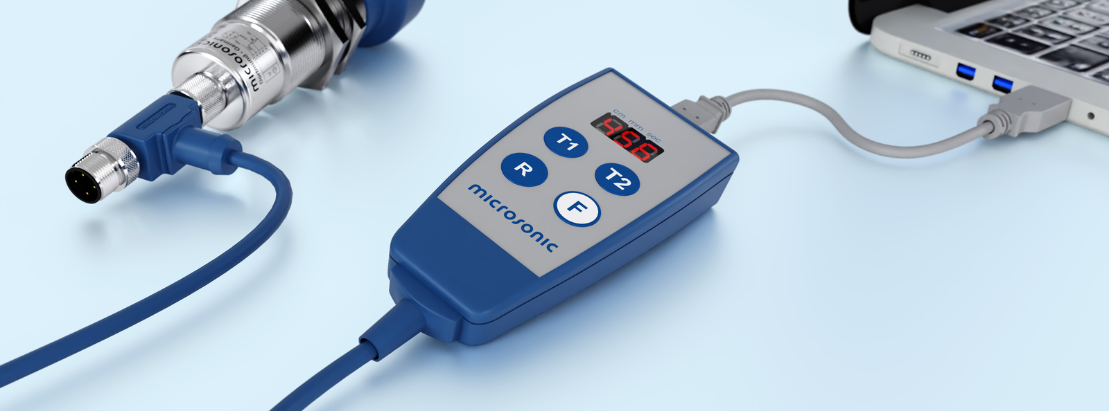
optionally permits the extensive parameterisation of lpc+ sensors. The LCA-2 LinkControl adapter , which is available as an accessory, can be used to connect lpc+ sensors to the PC.

Sensor über LCA-2 für die Programmierung am PC angeschlossen
LCA-2를 통해 프로그래밍을 위하여 PC에 연결된 센서.

Easy to synchronise

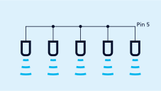
A number of lpc+ ultrasonic sensors can be run closely packed in applications synchronised to stop them from influencing one another. To this end, the sync mode has to be activated and all the sensors are to be electrically connected one to another with pin 5.

If more than 10 sensors must be synchronised, this can be carried out with the SyncBox1 , which is available as an accessory.

Synchronisation using pin 5
핀 5를 통한 동기화

IO-Link integrated

in version 1.1. The lpc+ ultrasonic sensors are equipped with Smart Sensor Profile, which creates more transparency between IO-Link devices.