







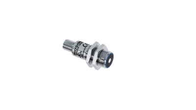
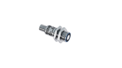
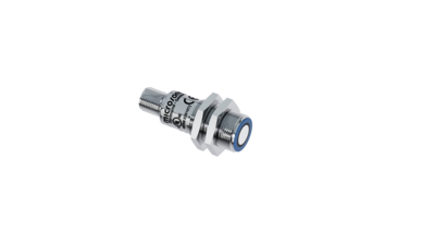
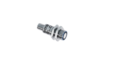
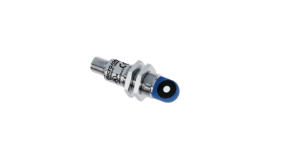
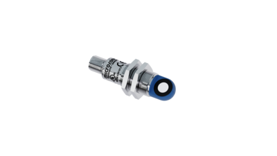
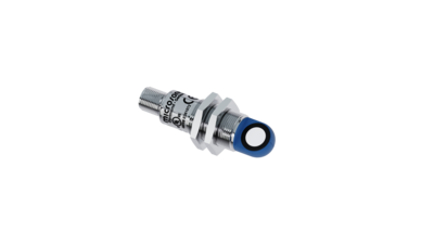
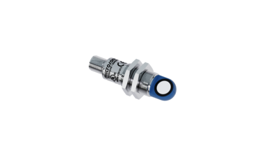

Auf dem Foto sind die pico+ Ultraschall-Abstandssensoren in den vier verschiedenen Tastweiten zu sehen.

pico+

새로운 M18 초음파센서 : 4검출 영역,2종류의 하우징 타입, 3종류의 출력 형태,1 IO-LINK

검출 영역
  • Symbolische Darstellung eines Ultraschallsensor mit einer Tastweite von 0,15 m.0.15 m
  • Symbolische Darstellung eines Ultraschallsensor mit einer Tastweite von 0,25 m.0.25 m
  • Symbolische Darstellung eines Ultraschallsensor mit einer Tastweite von 0,35 m.0.35 m
  • Symbolische Darstellung eines Ultraschallsensor mit einer Tastweite von 1,0 m.1.0 m
출력
  • Symbolische Darstellung 1 Push-Pull-Schaltausgang in pnp- und npn-Schaltungstechnik mit IO-Link-Schnittstelle
  • Symbolische Darstellung von einem Analogausgang
하우징 규격

하이라이트

  • Variant with 90° angled head
  • IO-링크 인터페이스새로운 산업 표준 지원 
  • 스마트 센서 프로필 IO-Link 장치 간 투명성 향상
  • 자동 동기화와 다중 동작 자동 동기화와 다중 동작
  • 120초 내 보정된 온도의 조건으로 작동하는 기능이 개선됨
  • 캐네디안, US 안전 기준 UL 인증 등록

기본 사항

  • 1 Push-Pull switching output pnp or npn basis
  • 4–20 mA, 0–10 V 아날로그 출력 전압 전류의 자동 변경
  • 20mm 에서 1.3m 까지의 4가지의 측정 범위
  • 5번 핀은 센서 설정을 위해 사용
  • 0.069 mm 에서  0.1 mm 의 분해능
  • 10~30V 작동 전압
  • 링크컨트롤(LinkControl) PC로 센서를 환경설정 

The pico+ ultrasonic sensors

are a compact series with M18 threaded sleeves and a housing length of only 41 mm. In addition to the variants with an axial beam direction, there is also a housing variant with a 90° angled head and radial beam direction. With four detection ranges from 20 mm to 1.3 m and three different output stages, this sensor family covers a wide range of applications.

Sensors with the Push-Pull output stage support SIO and IO link modes. Sensors with analogue output are optionally available with 4–20 mA current output or 0–10 V voltage output. In SIO mode, sensors are configured using the microsonic Teach-in procedure on pin 5.
사용 가능한 출력 단계는 두 가지입니다.

Symbolische Darstellung 1 Push-Pull-Schaltausgang in pnp- und npn-Schaltungstechnik mit IO-Link-Schnittstellepnp 또는 npn 회로에서 1개의 푸시-풀 스위칭 출력
Symbolische Darstellung von einem Analogausgang1개의 아날로그 출력 4–20 mA 또는 0–10 V

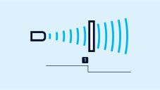
스위칭 출력이 있는 큐브 센서에는 세 가지 작동 모드가 있습니다.

  • 단일 스위칭 포인트
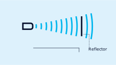
  • 양방향 반사 장벽
  • 윈도우 모드

하나의 스위칭 지점 티치 인

  • 원하는 거리에 물체를 놓으십시오- (1) 지점
  • +UB 선을 핀 5에 약 3 초 동안 접촉하십시오
  • 그런 다음 +UB 를 약 1 초 동안 다시 5 번 핀에 접촉하십시오.
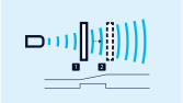
Teach-in of a switching point
스위칭 포인트의 티치-인
Teach-in of a two-way reflective barrier ultrasonic sensor
2방향 반사 장벽의 티치-인

고정 장착된 반사경이 있는 2방향 반사 장벽의 티치-인

  • 버튼 T2를 약 3초간 누릅니다.
  • 그런 다음 버튼 T2를 다시 약 10초간 누릅니다.

창 구성

단일 스위칭 출력에 두 개의 스위칭 포인트가 있는 경우, 절차는 아날로그 특성을 설정하는 것과 동일합니다.

NCC/NOC

상승/하강 아날로그 특성도 버튼을 통해 설정할 수 있습니다.

One green and one yellow LED

indicate the state of the output and support microsonic teach-in.

아날로그 특성 또는 두 개의 스위칭 포인트가 있는 창의 티칭
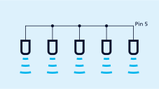
Synchronisation using pin 5
핀 5를 통한 동기화

Easy to synchronise

A number of pico+ sensors can be run closely packed in applications synchronised to stop them influencing one another. To this end, the sync mode has to be activated and all the sensors are to be electrically connected one to another with Pin 5.

If more than 10 sensors must be synchronised, this can be carried out with the SyncBox1, available as an accessory.

In instances of where a number of sensors are run at an IO-Link master, then the master's function is to assume synchronisation.

LinkControl

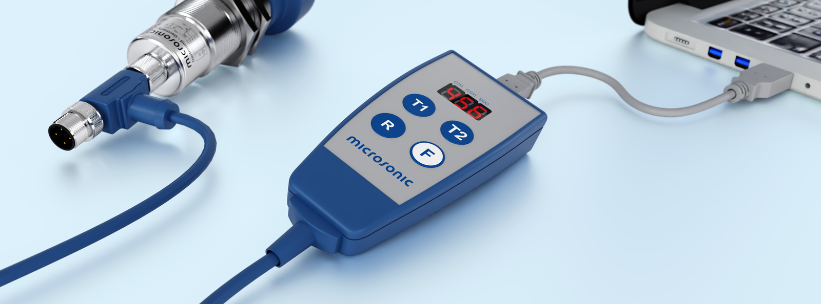
센서를 PC에 연결하는LinkControl-Adapter 를 통해 큐브 초음파 센서의 포괄적인 파라메터화를 허용합니다.

Sensor über LCA-2 für die Programmierung am PC angeschlossen
LCA-2를 통해 프로그래밍을 위하여 PC에 연결된 센서.

Updated to IO-Link version 1.1

The pico+ sensors with the extension „/A” in the order name are updated to IO-Link version 1.1 and support the Smart Sensor Profile. Please note that these sensor with the updated IO-Link version do not support IO-Link version 1.0 any longer. For example, when replacing pico+15/F with a pico+15/F/A you have to integrate the new device ID in the IO-Link master. In SIO mode, the sensors are compatible with each other.

The predecessor models pico+xxx/F can be found in the sensor archive.

특별한 요구 사항이 있습니까?

우리와 함께, 당신은 개별 솔루션을 쉽게 찾을 수 있습니다. 이것처럼 간단한 일은 없습니다.

당신의 어플리케이션에 대하여 말씀해 주십시오: +49 231 97 51 51-82.