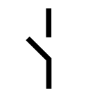
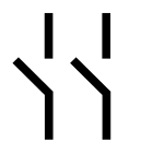
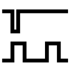
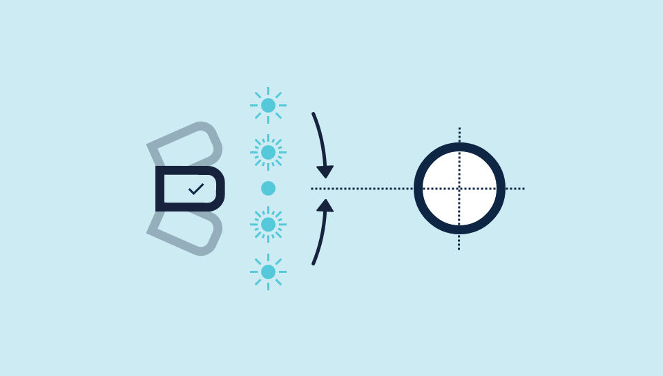
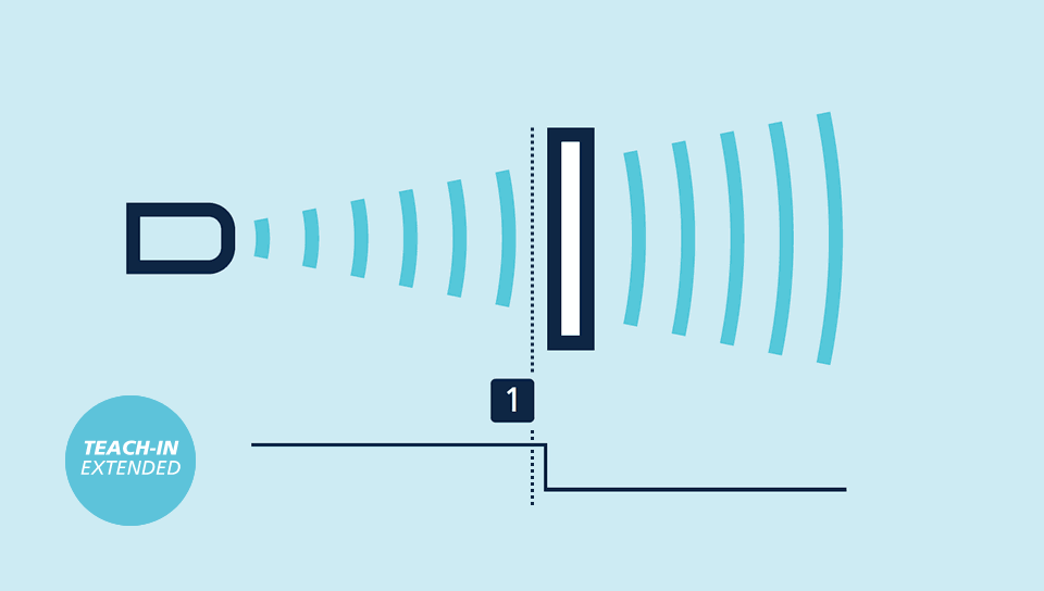
Per la configurazione di una finestra
con due punti di commutazione su un'unica uscita di commutazione, la procedura è la stessa dell'impostazione della caratteristica analogica.
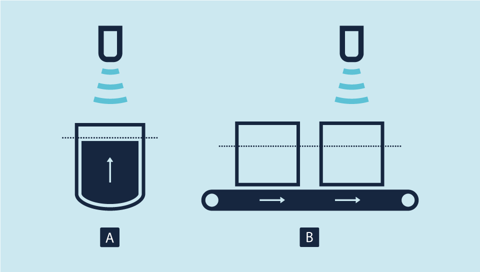
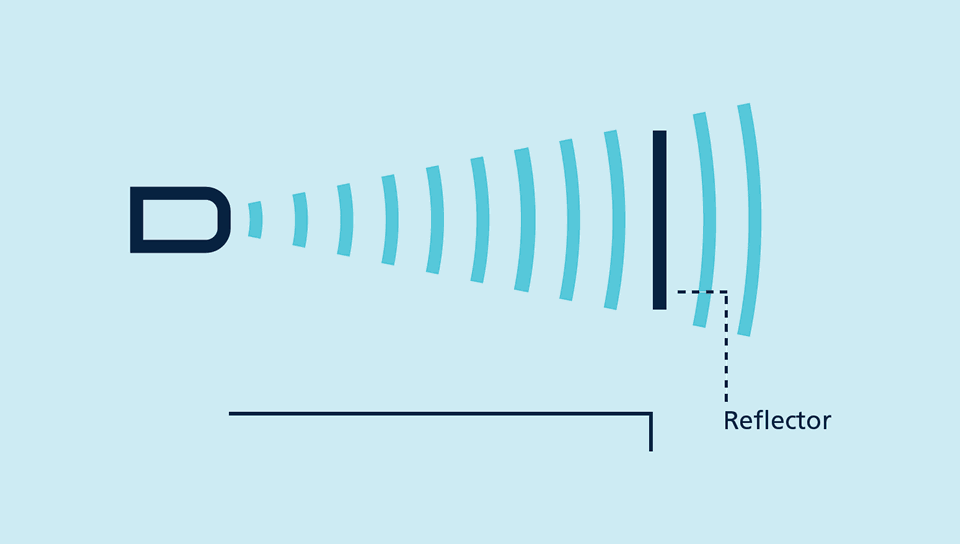
I sensori con uscita analogica
controllano il carico collegato all'uscita e passano automaticamente alla corrente di uscita da 4-20 mA o alla tensione di uscita da 0-10 V. Ciò garantisce un utilizzo estremamente pratico.
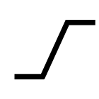
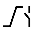
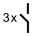
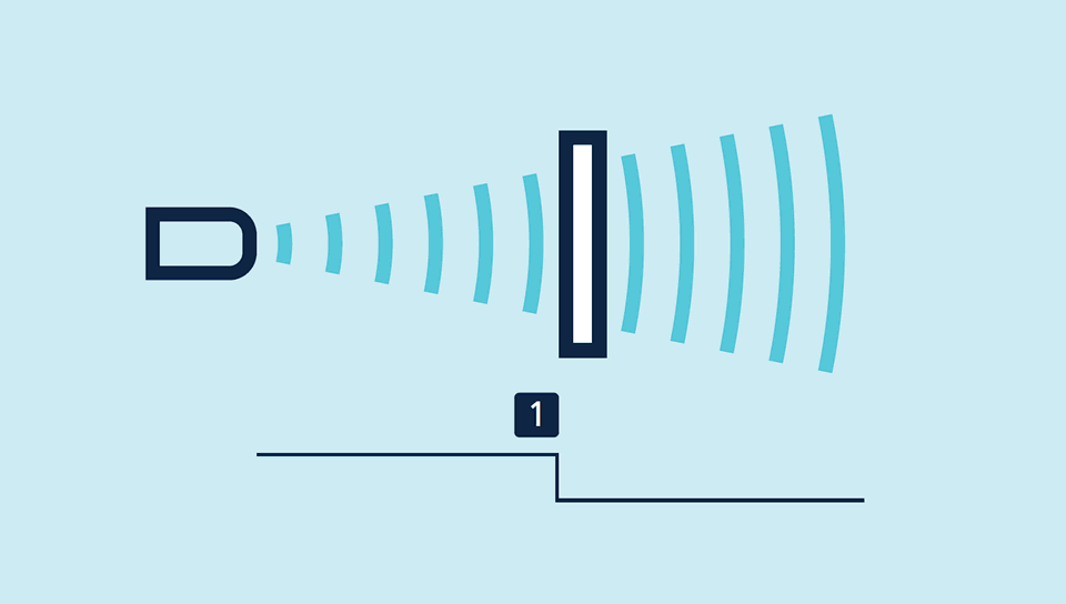
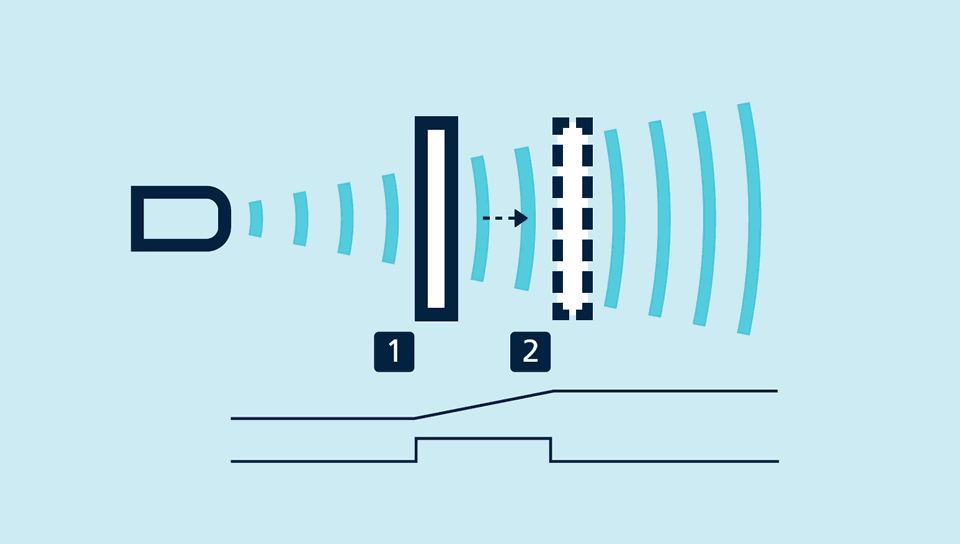
Il contatto NC/NA
e la curva caratteristica analogica ascendente/ discendente possono essere impostate anche tramite i pulsanti.
LinkControl
consente un'ampia parametrizzazione dei sensori ultrasonici cube. Tramite l’adattatore LinkControl LCA-2 disponibile come accessorio, è possibile collegare al PC i sensori cube.
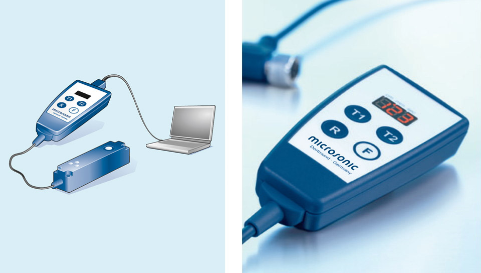
Sensore collegato tramite LCA-2 per la programmazione su PC
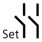
Semplice da sincronizzare
Nelle applicazioni in cui devono essere azionati più sensori ultrasonici, questi ultimi possono essere sincronizzati tra loro per evitare che si influenzino reciprocamente. A tale fine, tutti i sensori devono essere collegati tra loro con il pin 5.
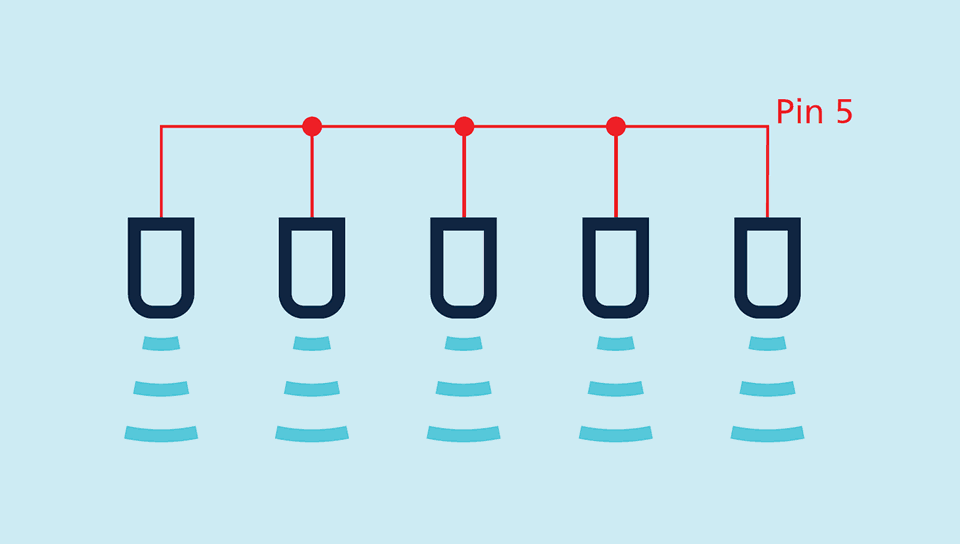
Sincronizzazione tramite il pin 5.
Se fosse necessario sincronizzare più di 10 sensori, è possibile farlo mediante la SyncBox1. La sincronizzazione tramite il pin 5 è possibile anche in modalità operativa IO-Link.