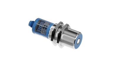
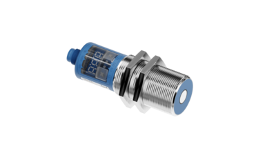
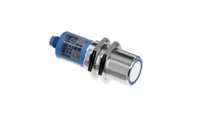
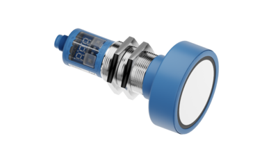
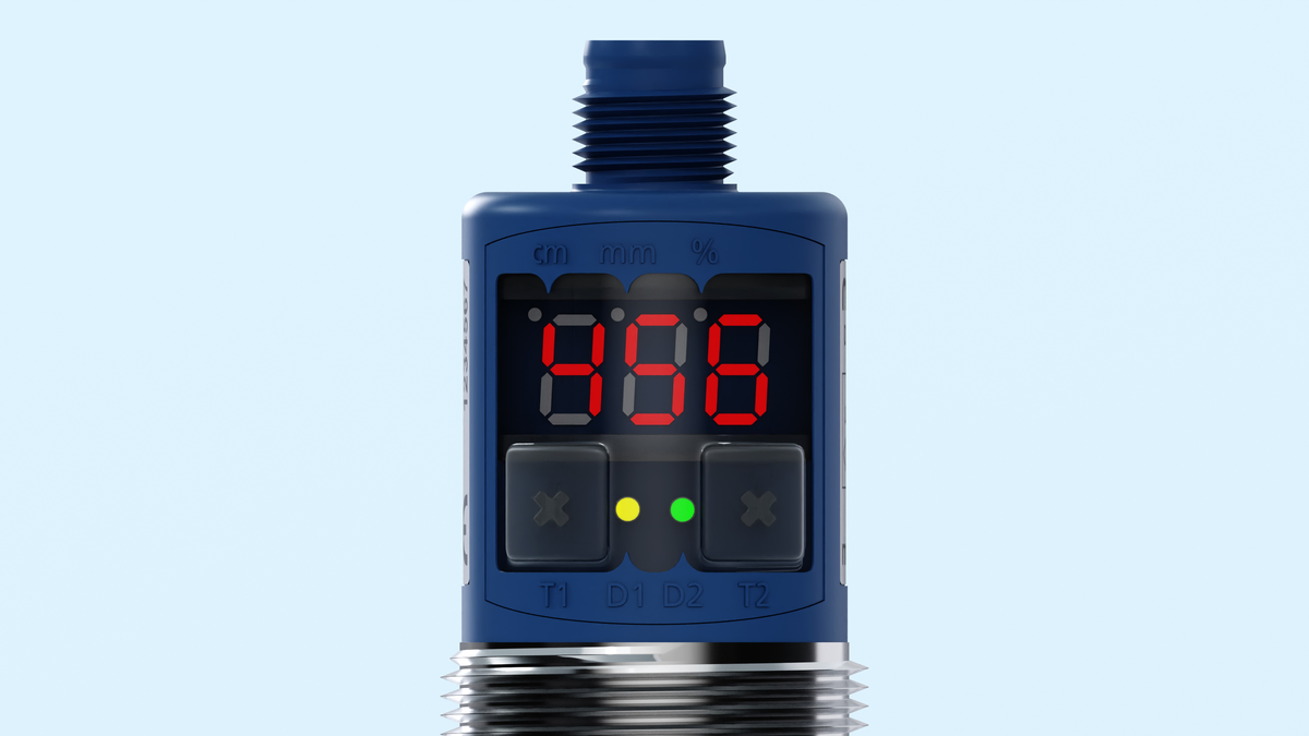
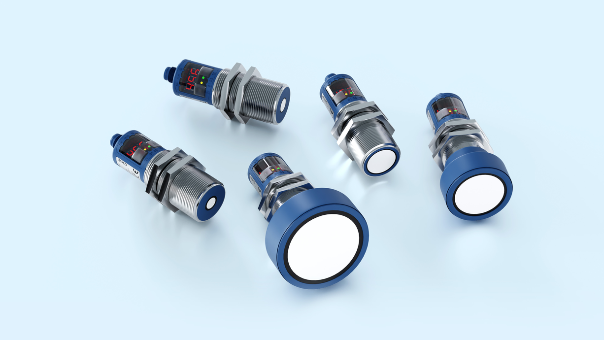
Auf dem Bild sind die mic+ Ultraschallsensoren mit Digital-Display in den fünf verschiedenen Tastweiten

mic+

mic+ sensors are available in four device variants with five different sensing ranges.

Detection ranges:
  • Symbolische Darstellung eines Ultraschallsensor mit einer Tastweite von 0,25 m.0.25 m
  • Symbolische Darstellung eines Ultraschallsensor mit einer Tastweite von 0,35 m.0.35 m
  • Symbolische Darstellung eines Ultraschallsensor mit einer Tastweite von 1,3 m.1.3 m
  • Symbolische Darstellung eines Ultraschallsensor mit einer Tastweite von 3,4 m.3.4 m
  • Symbolische Darstellung eines Ultraschallsensor mit einer Tastweite von 6,0 m.6.0 m
Outputs:
  • Symbolische Darstellung 1 Push-Pull-Schaltausgang in pnp- und npn-Schaltungstechnik mit IO-Link-Schnittstelle
  • Symbolische Darstellung 1 Schaltausgang
  • Symbolische Darstellung 2 Schaltausgänge
  • Symbolische Darstellung von einem Analogausgang
  • Symbolische Darstellung 1 Analogausgang mit einem zusätzlichen pnp-Schaltausgang
Threaded sleeve:

Highlights

  • Digital display with direct measured value output in mm/cm or %
  • IO-Link interfacefor support of the new industry standard
  • Numeric configuration of the sensor using digital display permits complete advance configuration of the sensor
  • Automatic synchronisation and multiplex operation for simultaneous operation of up to ten Sensors in close quarters
  • UL Listed to Canadian and US safety standards

Basics

  • 1 Push-Pull switching output pnp or npn basis
  • 1 or 2 switching outputs in pnp or npn variants
  • Analogue output 4–20 mA and 0–10 V with automatic switching between current and voltage outputs
  • Analogue output plus 1 pnp switching output
  • 5 detection ranges with a measurement range of 30 mm to 8 m
  • microsonic Teach-in by using button T1 and T2
  • 0.025 mm to 2.4 mm resolution
  • Temperature compensation
  • 9–30 V operating voltage
  • LinkControlfor configuration of sensors from a PC

Sensor matrix

The sensor matrix provides an overview of the standard range of the mic+ sensor family. Select the desired operating range and available outputs by clicking on the matrix.

The mic+ sensor family

in the M30 housing design covers a measuring range from 30 mm to 8 m with its five sensing ranges. The internal resolution of the distance measurement is 0.025 or 2.4 mm, depending on the sensing range. All sensors have integrated temperature compensation.

TouchControl with LED display

With TouchControl

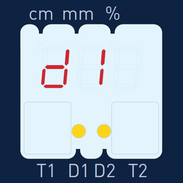
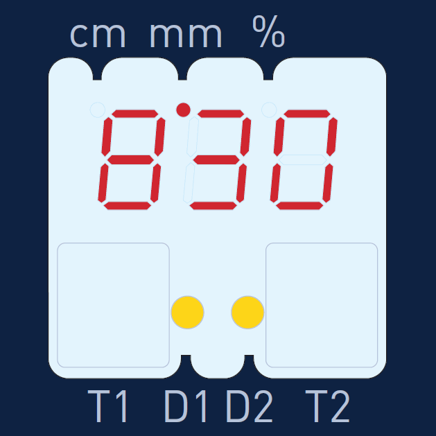
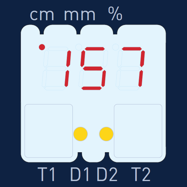
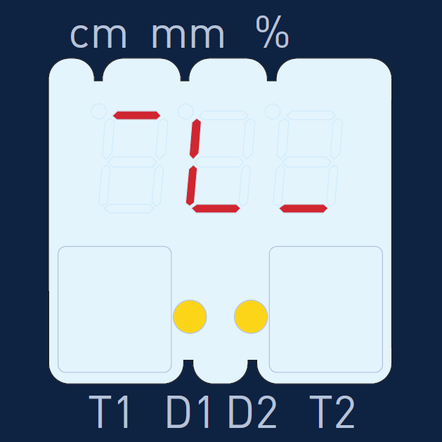
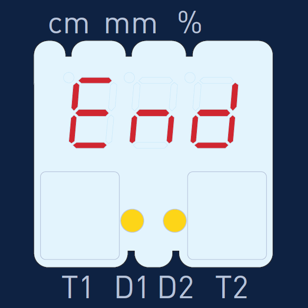
All settings are made on the sensors. The easy-to-read three-digit LED display constantly shows the current distance value and automatically switches between mm and cm display. Two buttons located below the LED display are used to call up the parameterisation and navigate through the self-explanatory menu structure. The switching points of the switching outputs and the window limits for the analogue output can be preset numerically using the digital display without the object to be scanned having to be within the detection range. This makes it possible to completely adjust the sensor without the aid of auxiliary reflectors, even outside the actual application.

Two three-colour LEDs

always indicate the current status of the switching outputs or the analogue output.

Additional functions (add-ons)

are available as options within the TouchControl menu structure: For example, the measured distance value can be applied with the ten-stage software filter from F00 (direct measured value output without filter effect) to P09 (very strong filtering and measured value attenuation). High measured value attenuation is useful for level measurements with wave movements or in situations where parts can sporadically fly between the sensor and the actual measuring surface. The F01 filter is set as standard. This means that the sensors are preset ex works for fast counting and control processes. As an additional function, the switching hysteresis of the switching outputs can be changed in their standard settings if required. The LED display can be permanently switched off or dimmed.

Four different starting levels

are available for all five detection ranges:

Symbolische Darstellung 1 Push-Pull-Schaltausgang in pnp- und npn-Schaltungstechnik mit IO-Link-Schnittstelle1 switching output in Push-Pull circuitry
Symbolische Darstellung 1 Schaltausgang1 switching output, optionally in pnp or npn circuitry
Symbolische Darstellung 2 Schaltausgänge2 switching outputs, optionally in pnp or npn circuitry
Symbolische Darstellung von einem Analogausgang1 analogue output 4–20 mA and 0–10 V
Symbolische Darstellung 1 Analogausgang mit einem zusätzlichen pnp-Schaltausgang1 analogue output with an additional pnp switching output

Analogue sensors

verify the load connected to the output and automatically switch to 4–20 mA current output and 0–10 V voltage output depending on the resistance value. The load verification by the sensor is always initiated upon connection of the operating voltage.

In the add-on menu of TouchControl, the user can, however, also preset the sensor to current or voltage output. In this menu, the measuring value output on the LED display with analogue sensors can additionally be changed to indicate percentage. The window limits of the analogue characteristic curve then correspond to the 0% or the 100% value respectively.

Synchronisation

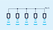
of up to ten sensors automatically also operates in a mixed configuration of sensors with different detection ranges. The measurement repetition rate is then determined by the sensor with the largest detection range. If the sensors are electrically connected via pin 5 of the M12 circular connector, the synchronisation is active. In synchronised operation, all sensors initiate the measuring process at exactly the same time. With relatively narrow mounting distances between the sensors, a sensor may also receive echo signals from an adjacent sensor.

This can be used as an advantage, e.g. to broaden a sensor’s detection range.
Synchronisation using pin 5
Synchronisation via pin 5

If more than 10 sensors need to be synchronised, this can be achieved using the SyncBox1, which is available as an accessory.

Multiplex operation 

ensures that each sensor can only receive echo signals from its own transmission pulse, which completely avoids any interference between the sensors (crosstalk).

Each sensor is assigned an address from 1 to 10 for this purpose in the add-on menu. The sensors then work in multiplex mode and carry out their measurements one after the other in ascending address order.

The setting of a switching or analogue output

is either carried out by means of numerically entering the desired distance values  or by means of a Teach-in procedure.
Thanks to this, the user can select the preferred setting mode.

In the microsonic Teach-in process

the object to be detected must be placed in the desired distance (1) to the sensor. The button assigned to the output must then be pressed until (or ) appears on the LED display. Finally, the Teach-in procedure must be confirmed by a further short keystroke. Ready.
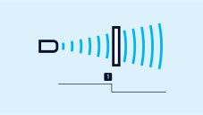
Teach-in of a switching point
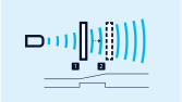
Teach-in of an analogue characteristic curve or a window with two switching points

To set an analogue output

the object to be detected must first be placed on the sensor-close window limit (1) and the key assigned to the output must be pressed until appears on the display. Then, the object to be detected must be moved to the sensor-distant window limit (2) and the Teach-in procedure must be terminated by a further short keystroke. Ready.

To set window mode with two switching points, the same procedure applies to one switching output.

normally closed/normally open

The switching outputs and rising/falling characteristic curve for the analogue sensors can also be set using the teach-in procedure. To do this, press and hold the button associated with the output until the symbol or appears on the display. Each additional press of the button switches between the settings normally open/normally closed ( / ) or rising/falling (  / ). After approx. 10 seconds, the new setting is automatically applied.
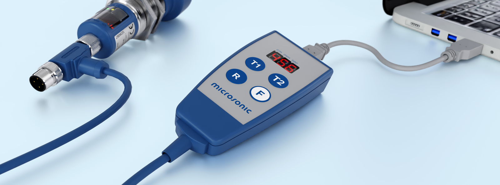

mic+ Sensor über LCA-2 für die Programmierung am PC angeschlossen
Sensor connected to the PC via LCA-2 for programming

LinkControl

consists of the LinkControl adapter and the LinkControl software and allows the mic+ sensors to be set up using a PC or laptop under all common Windows® operating systems. All settings from the TouchControl menu can be read out during operation, edited on the PC, temporarily stored and written back to the sensor. In particular, the two measurement recorders for visualising the distance values help in the development of solutions for complex automation tasks.

IO-Link integrated

in version 1.1 for sensors with switching output.

Pin assignment

 Icon 
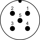
PinPNPNPNPNPNPNAnalogue output1 PNP output
+ analogue
Colour coding
Standard colour
1+UB+UB+UB+UB+UB+UBbrown
3-UB-UB-UB-UB-UB-UBblue
4DED2E2-Dblack
2--D1E1I/UI/Uwhite
5COMCOMCOMCOMCOMCOMgrey

View of built-in plug

Steckerbelegung mic+

Settings

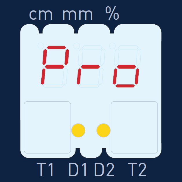
Press both buttons until Pro for programming appears on the LED display. Select the output to be set (d1, d2 or IU, depending on the sensor type). Set the switching point (or the sensor-proximal window limit for an analogue output) on the LED display in mm/cm. If window operation is desired for the switching output, also set the rear window limit (or, in the case of an analogue output, the window limit far from the sensor) in mm/cm. Select between normally closed/normally open (or between falling/rising characteristic curve for an analogue output). Finished.


For numerical input, the object to be scanned does not have to be within the sensor's detection range!

You have special requirements?
Nothing as simple as that.

With us, you can easily find an individual solution. Let us talk about your application: +49 231 97 51 51-82.