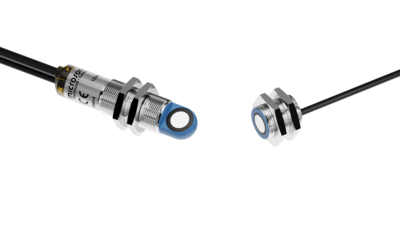
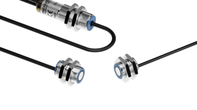
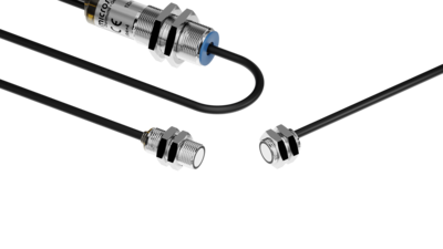
The task of double-sheet control
is to identify two or more pieces or sheets inadvertently adhering together.
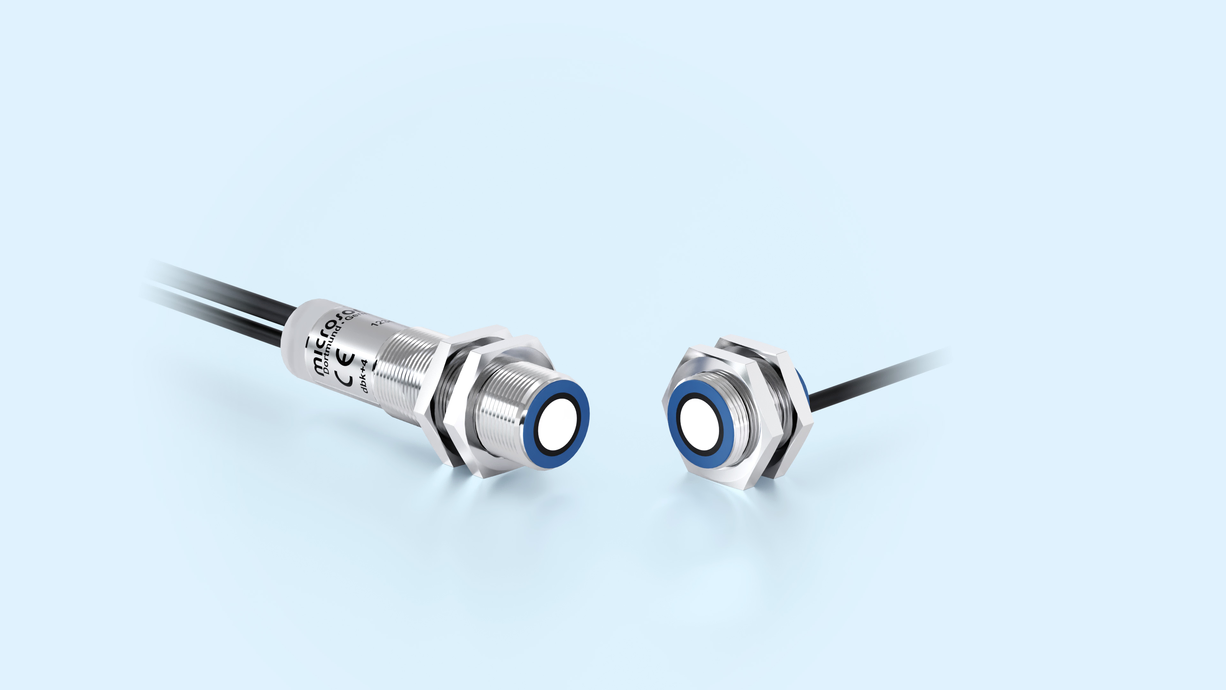

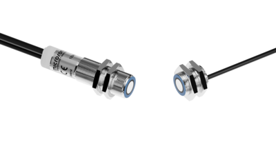
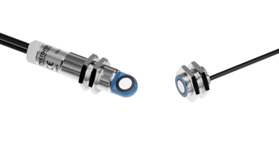
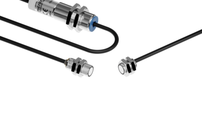
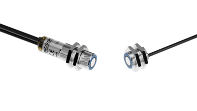
The latest type of ultrasonic double sheet control. Three variants: for all imaginable fitting positions.
 Standard: 20 g/m2 - 1.200 g/m2Thin: <20 g/m2Thick: >1.200 g/m2





The sensor matrix gives an overview of the entire sensor family. Make your choice based on housing variants and sensor compentents and click in the matrix.


is to identify two or more pieces or sheets inadvertently adhering together.
A high-frequency ultrasonic transmitter beams against the sheet from the underside. The beamed signal induces the material to vibrate. The effect of these vibrations is a very small sonic wave on the other side of the sheet being spread. This wave is evaluated by the ultrasonic receiver on the opposite side. The signal from the stacked sheet ("double sheet") is so weak that it hardly gets to the receiver.
The dbk+4 detects missing, single and double sheet.
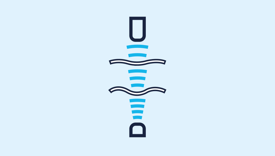
The new dbk+4 has 3 control inputs by means of which 3 working range can be preselected. The standard working ranges covers the sheet material weight range from 20 g/m2 to 1,200 g/m2. Extremely thin materials such as Bible printing paper with a weight per unit area of less than 20 g/m2 are scanned with the use of the "Thin" setting.
The "Thick" setting is available for paperboard containers and fine-corrugated card. Changes between the working ranges can be undertaken under on-going operations. A Teach-in for the material to be scanned is not necessary. If the 3 control inputs stay unconnected, then the dbk+4 operates in the standard working range. As such, a very broad material spectrum can be scanned.
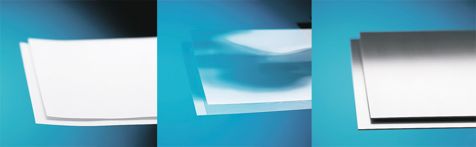
The Teach-in function is additionally available for materials which cannot be scanned with one of the three working ranges. A material Teach-in is done by inserting a single sheet into the double-sheet control. The C3 control input is then placed to logic 1 level for at least 3 seconds. Materials with non-homogeneous elements must be moved during the Teach-in phase so that the dbk+4 detect them. Success with a Teach-in operation is shown by a green LED. The material can now be scanned. The Teach-in makes it possible to scan material from thin Washi to wafers glued with a water film.
The recommended spacing between transmitter and receiver is 40 mm (or 20 mm with dbk+4/M12/CD/M18 ER+S). If needed, this spacing can be adapted to the local conditions in the 20 to 60 mm range. For the matter of commissioning, this can be done by means of a simple Teach-in or with the LinkControl parameterisation software.
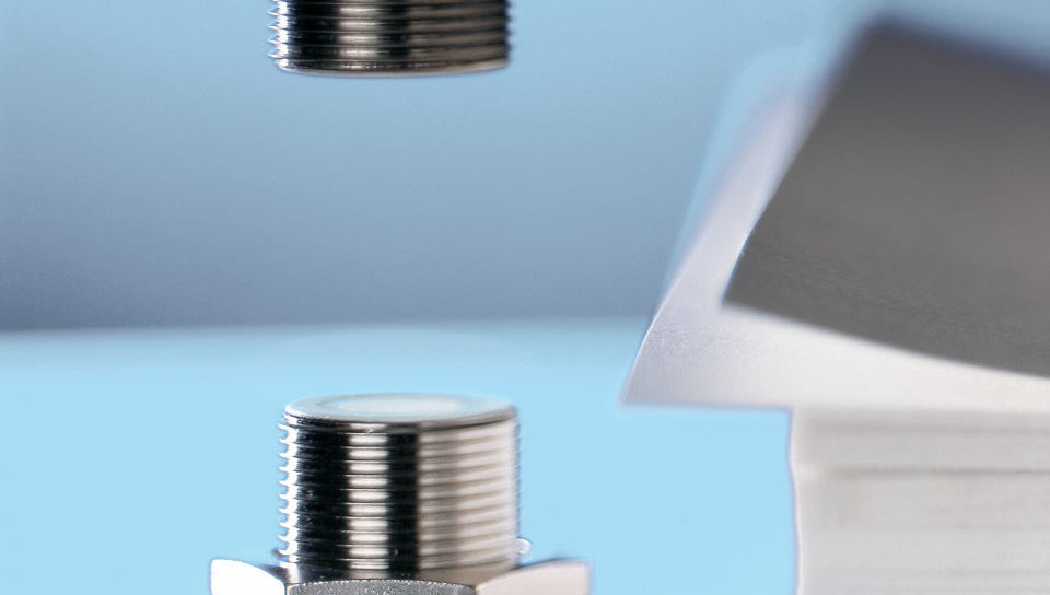
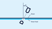
With papers and thin films, the double-sheet control is effected perpendicularly to the material; flapping does not impair the function. In the case of fine-corrugated card, thin sheet metal, wafers or thicker plastic films (e. g. credit cards), the dbk+4 should to be mounted at a specific angle of inclination α to the material running through.
The dbk+4 operates as standard in the free-run mode. This means that the dbk+4 cyclically carries out measurements at a high measuring rate. Under ongoing operations, the working range can be changed and a teach-in carried out by means of the C1 to C3 control inputs.
| C1 | C2 | C3 | |
|---|---|---|---|
| Standard | 0 | 0 | 0 |
| Thick | 0 | 1 | 0 |
| Thin | 1 | 0 | 0 |
| Teach-in-Mode | 1 | 1 | 0 |
| Teach-in | 1 | 1 | 1 |
Should, on the other hand, measurements be undertaken in applications with continous feed, then an external trigger signal can trigger a measurement. This function is parameterised with the aid of the LinkControl- Software. A choice can be made between edge trigger and level trigger. The C2 control input then assumes the function of the trigger input (tr).
| C1 | C2 | C3 | |
|---|---|---|---|
| Standard | 0 | tr | 0 |
| Thin | 0 | tr | 1 |
| Teach-in-Mode | 1 | tr | 0 |
| Teach-in | 1 | tr | 1 |
Under ongoing operations, the working range can be changed by means of the C3 control input.
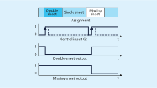
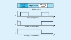
in version 1.1.5. The double-sheet control dbk+4 ultrasonic sensors are equipped with Smart Sensor Profile, which creates more transparency between IO-Link devices.
cover all imaginable fitting positions.
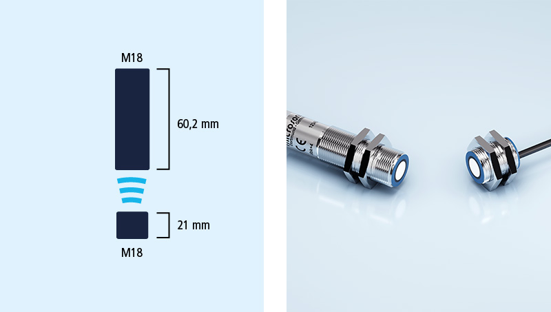
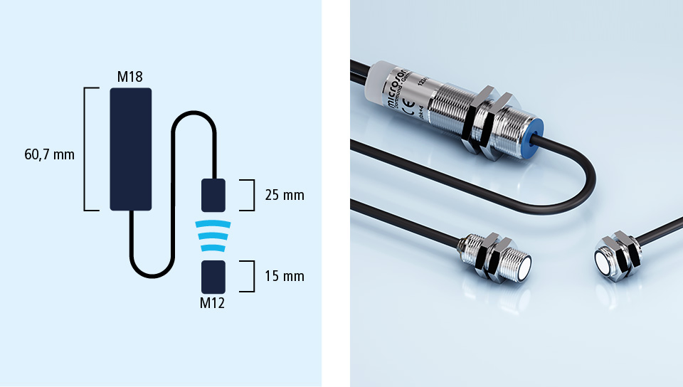
The standard: receiver and all the evaluation electronics are housed in an M18 threaded sleeve, which is only 60.2 mm long. The transmitter is housed in an M18x21 mm threaded sleeve and a 2-pin plug connects it to the receiver.
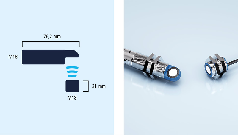
As with the standard, but here the receiver is arranged at right angles to the M18 threaded sleeve.
The M12-heads variant has an optimum spacing of 20 mm between transmitter and receiver.
With us, you can easily find an individual solution. Let us talk about your application: +49 231 97 51 51-82.