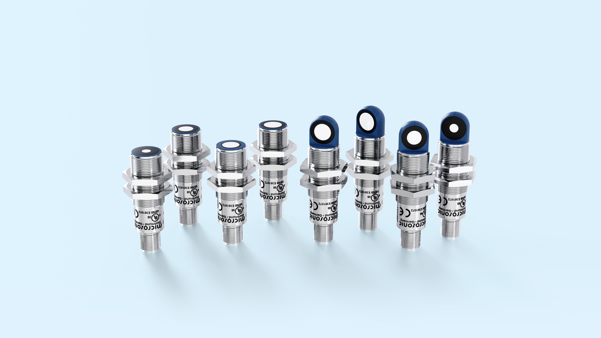








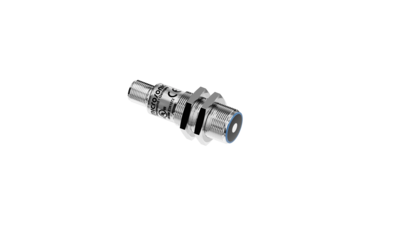
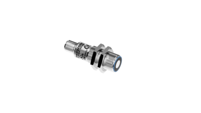
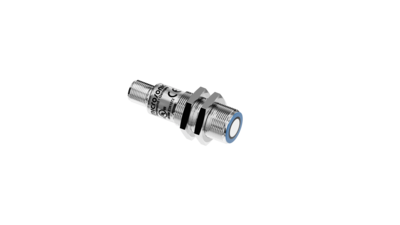
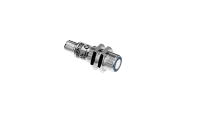
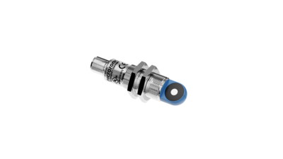
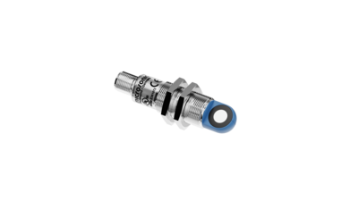
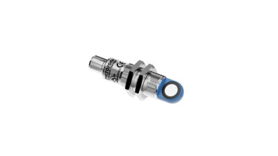
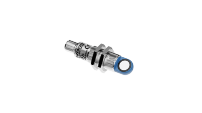

Auf dem Foto sind die lpc+ Ultraschall-Abstandssensoren in den vier verschiedenen Tastweiten zu sehen.

lpc+

lpc+ well equipped: 2 Push-Pull switching outputs or 1 Push-Pull switching output with an analogue output in M18 housing.

Detection ranges:
  • Symbolische Darstellung eines Ultraschallsensor mit einer Tastweite von 0,15 m.0.15 m
  • Symbolische Darstellung eines Ultraschallsensor mit einer Tastweite von 0,25 m.0.25 m
  • Symbolische Darstellung eines Ultraschallsensor mit einer Tastweite von 0,35 m.0.35 m
  • Symbolische Darstellung eines Ultraschallsensor mit einer Tastweite von 1,0 m.1.0 m
Outputs:
  • Symbolische Darstellung 1 Analogausgang mit einem zusätzlichen pnp-Schaltausgang mit IO-Link-Schnittstelle
  • Symbolische Darstellung 2 Schaltausgänge mit IO-Link-Schnittstelle
Threaded sleeve:

Highlights

  • Analogue output 4–20 mA or 0–10 V plus 1 Push-Pull switching output in M18 design
  • IO-Link interfacefor support of the new industry standard 
  • Smart Sensor Profiles more transparency between IO-Link Devices
  • Improved temperature compensation adjustment to working conditions within 120 seconds
  • UL Listed to Canadian and US safety standards

Basics

  • 2 Push-Pull switching outputs pnp or npn basis
  • 4 detection ranges with a measurement range of 20 mm to 1.3 m
  • microsonic Teach-in on pin 5
  • 0.1 mm resolution
  • 10–30 V operating voltage
  • LinkControlfor configuration of sensors from a PC

Sensormatrix

The sensor matrix gives an overview of standard sensors from lpc+ family. Make your choice based on operating range and available outputs and click in the matrix.

The lpc+ ultrasonic sensors

are optionally equipped with two Push-Pull switching outputs or an analogue output plus a Push-Pull switching output. The compact series with M18 threaded sleeves coves four detection ranges from 20 mm to 1.3 m.

Ultrasonic sensors with the Push-Pull output stage support SIO and IO-Link modes. Sensors with analogue output are optionally available with 4–20 mA current output or 0–10 V voltage output.In SIO mode, sensors are configured using the microsonic Teach-in procedure on pin 5.
 

two output stages:

2 output stages and 4 detection ranges available:

Symbolische Darstellung 2 Schaltausgänge mit IO-Link-Schnittstelle2 Push-Pull-switching outputs, optionally in pnp or npn circuitry with IO-Link interface
Symbolische Darstellung 1 Analogausgang mit einem zusätzlichen pnp-Schaltausgang mit IO-Link-Schnittstelle1 Push-Pull switching output and analogue output 4–20 mA or 0–10 V

Sensors with switching output have three operating modes:

  • Single switching point
  • Two-way reflective barrier
  • Window mode

Teach-in of a single switching point

  • Place object to be detected (1) at the desired distance
  • Apply +UB to pin 5 for about 3 seconds
  • Then apply +UB to pin 5 again for about 1 second
Teach-in of a switching point
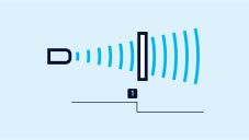
Teach-in of a two-way reflective barrier ultrasonic sensor
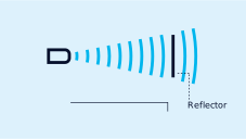
Teach-in of a two-way reflective barrier

Teach-in of a two-way reflective barrier

with a fixed reflector

  • Apply +UB to pin 5 for about 3 seconds
  • Then apply +UB to pin 5 again for about 10 seconds

For configuration of a window

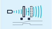
  • Place object at the near edge of the window (1)
  • Apply +UB to pin 5 for about 3 seconds
  • Then move the object to the far edge of the window (2)
  • Then apply +UB to pin 5 again for about 1 seconds
Teach-in of an analogue characteristic or a window with two switching points

NCC/NOC

and rising/falling analogue characteristic curve can also be set via pin 5.

LinkControl

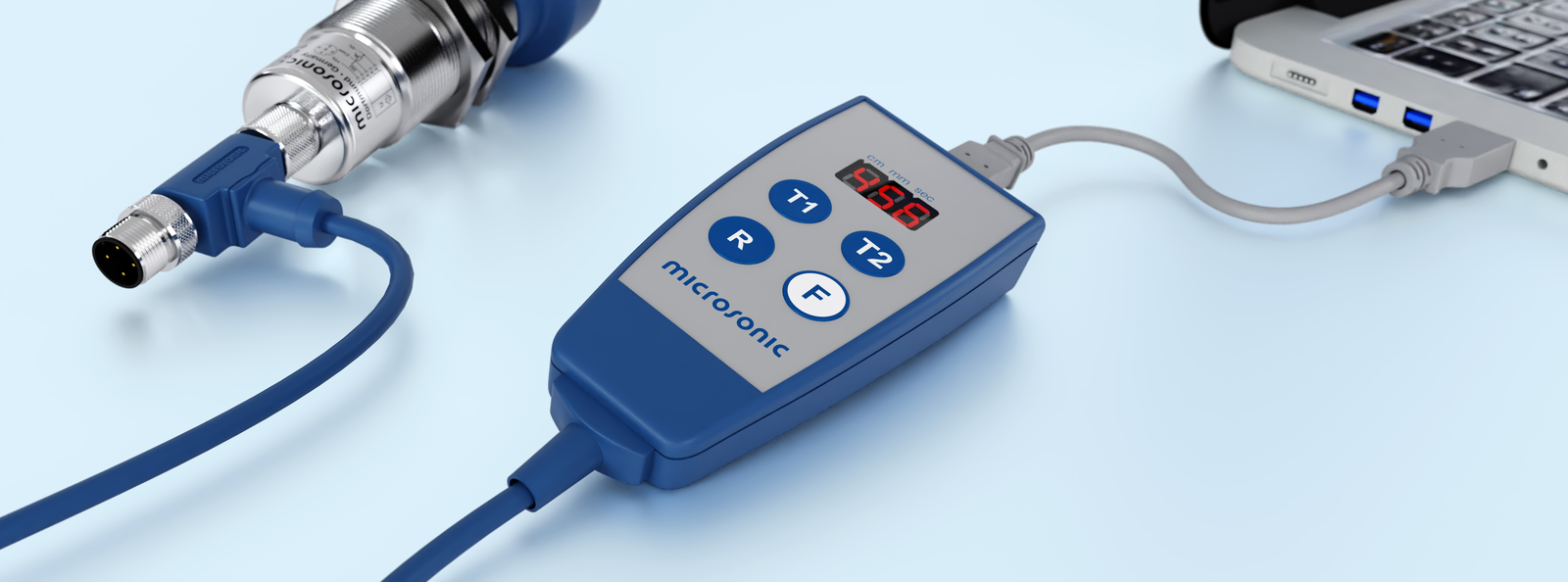
optionally permits the extensive parameterisation of lpc+ sensors. The LCA-2 LinkControl adapter , which is available as an accessory, can be used to connect lpc+ sensors to the PC.

Sensor über LCA-2 für die Programmierung am PC angeschlossen
Sensor connected to the PC via LCA-2 for programming

Easy to synchronise

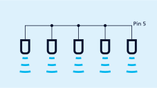
A number of lpc+ ultrasonic sensors can be run closely packed in applications synchronised to stop them from influencing one another. To this end, the sync mode has to be activated and all the sensors are to be electrically connected one to another with pin 5.

If more than 10 sensors must be synchronised, this can be carried out with the SyncBox1 , which is available as an accessory.

Synchronisation using pin 5

IO-Link integrated

in version 1.1. The lpc+ ultrasonic sensors are equipped with Smart Sensor Profile, which creates more transparency between IO-Link devices.

You have special requirements?
Nothing as simple as that.

With us, you can easily find an individual solution. Let us talk about your application: +49 231 97 51 51-82.

AI Bild mit einer Frau mit einem freundlichen Lächeln und direktem Blick. Sie trägt ein Headset.