lcs ultrasonic sensors

Sensor matrix of standard sensors

Overview

Ultrasonic sensors in the lcs series in cuboidal housing with lateral sound exit are available in three device variants with three different detection ranges.

download sensor line as pdf

Highlights

  • Up to 3 pnp switching outputs
  • Automatic synchronisation for simultaneous operation of up to ten sensors in close quarters

Basics

  • 2 or 3 switching outputs in pnp variant
  • Analogue output 4–20 mA and 0–10 V with automatic switching between current and voltage outputs
  • 3 detection ranges with a measurement range of 30 mm to 2 m
  • microsonic Teach-in on pin 5
  • 0.18 mm resolution
  • Temperature compensation
  • 9–30 V operating voltage
  • LinkControl for configuration of sensors from a PC

Description

The lcs sensors

have a block-like plastic housing with four fixation bores, two of which are already equipped with M4 threaded bushings for eased mounting.

Two or three LEDs

indicate all operating statuses.

Three detection ranges and two output stages are available for selection:

2 pnp switched outputs
3 pnp switched outputs
1 analogue output 4–20 mA and 0–10 V

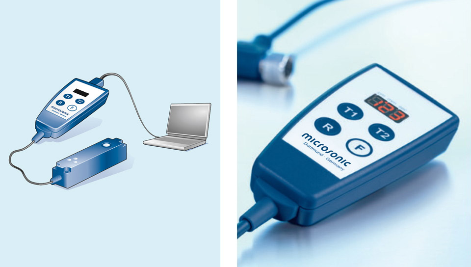
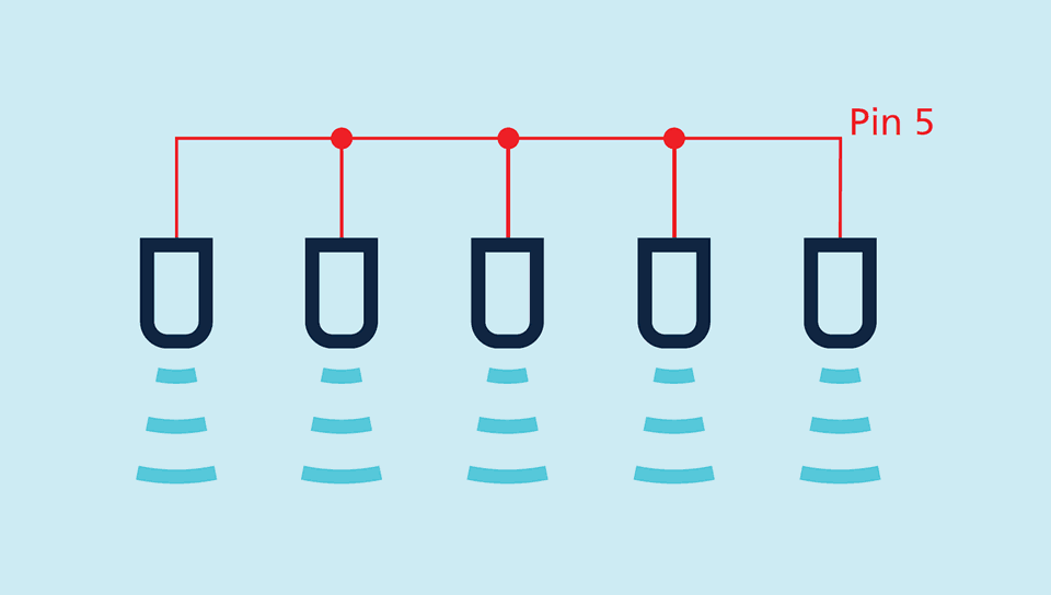
Via pin 5 at the M12 circular connector,

(Com input), the Ics sensors are set (Teach-in): Switched output D1 is set by connecting pin 5 to +UB, while switched output D2 is set by connecting pin 5 to –UB. Also the sensors with analogue output are set via pin 5.

The Ics sensors with switched output offer three operating modes:

  • Single switching point
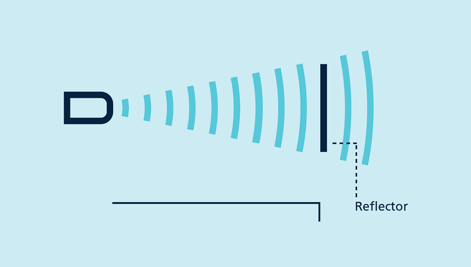
  • Two-way reflective barrier
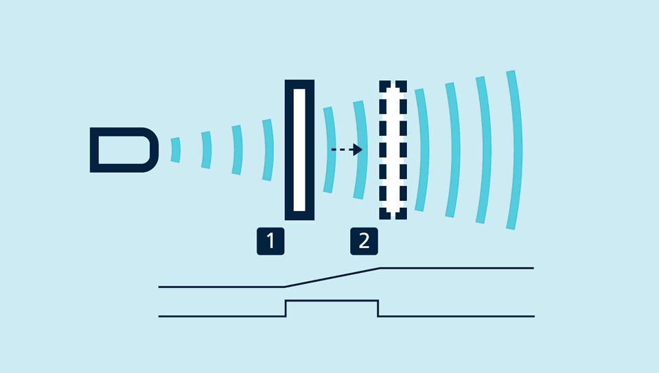
  • Window mode

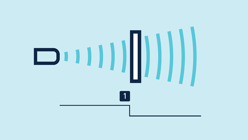
Teach-in of a single switching point

  • Place object to be detected (1) at the desired distance
  • Apply +UB to pin 5 for about 3 seconds
  • Then apply +UB to pin 5 again for about 1 seconds

Teach-in of a switching point

 Teach-in of a two-way reflective barrier

with a fixed reflector

  • Apply +UB to pin 5 for about 3 seconds
  • Then apply +UB to pin 5 again for about 10 seconds

Teach-in of a two-way reflective barrier

For configuration of a window

  • Place object at the near edge of the window (1)
  • Apply +UB to pin 5 for about 3 seconds
  • Then move the object to the far edge of the window (2)
  • Then apply +UB to pin 5 again for about 1 seconds

Teach-in of an analogue characteristic or a window with two switching points

NCC/NOC

and rising/falling analogue characteristic curve can also be set via pin 5.

The analogue sensor

checks the load connected to the output and then automatically switch to 4–20 mA current output or 0–10 V voltage output to ensure maximum ease of handling.

The Ics-25/DDD is equipped with three pnp switched outputs

which are set with the help of the Link-Control adapter LCA-2. In addition to this “offline” programming, all Ics sensors can also be parameterised on the PC with the LCA-2 and the Link-Control software .

Sensor connected to the PC via LCA-2 for programming

Synchronisation

permits the simultaneous use of multiple mic sensors in an application. To avoid mutual interference, the sensors can be synchronised with one another. To do this, all the sensors are electrically connected on pin 5.

Synchronisation using pin 5
Top