• erfassungsbereiche_en_1046x850.jpg

Detection Zones

The detection zones of ultrasonic sensors

 The most important criterion to bear in mind when selecting an ultrasonic sensor is its detection range and the associated three-dimensional detection zone.

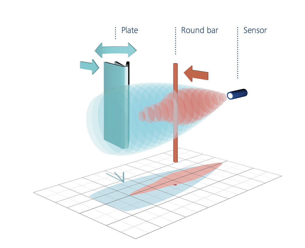
In measuring the sensors various standard reflectors are introduced into the detection zones from the side and the points at which these reflectors are detected by the sensor are marked.

Objects may be introduced into the detection zone from any direction.

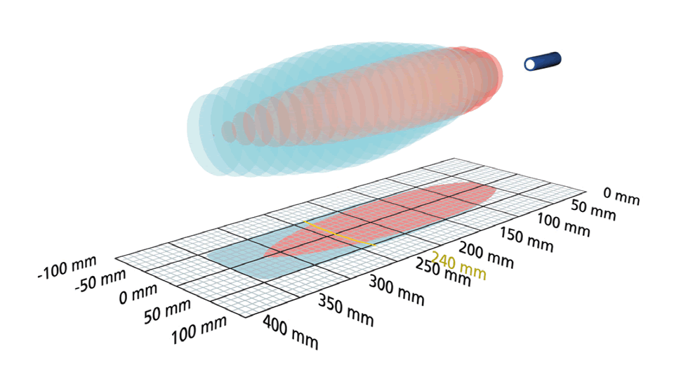
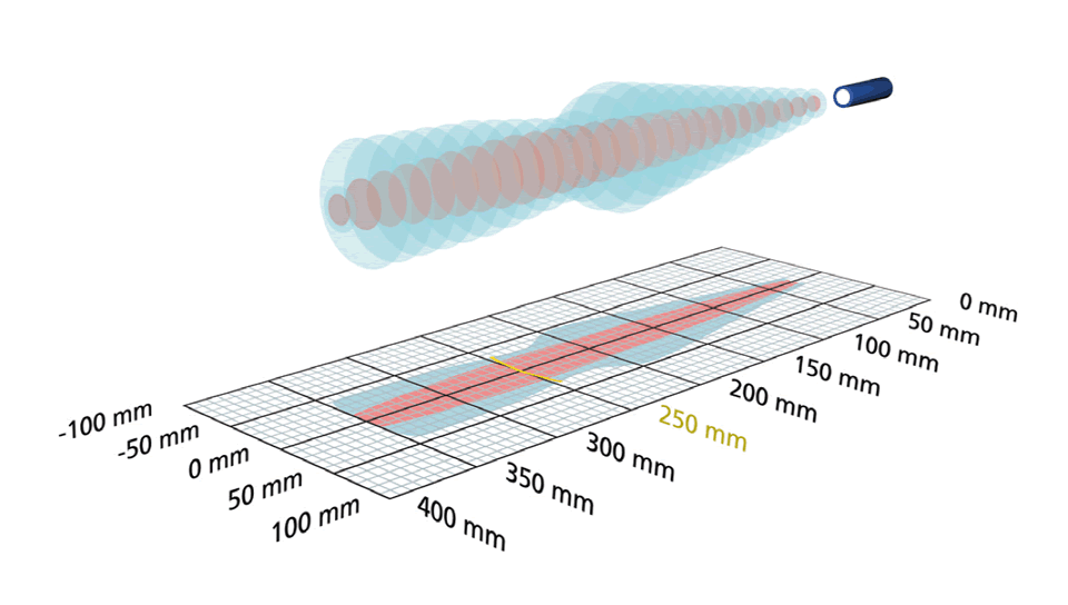
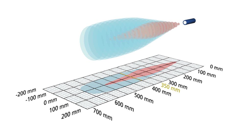
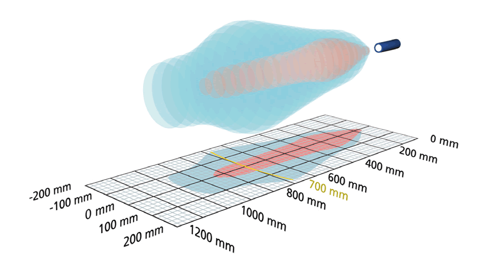
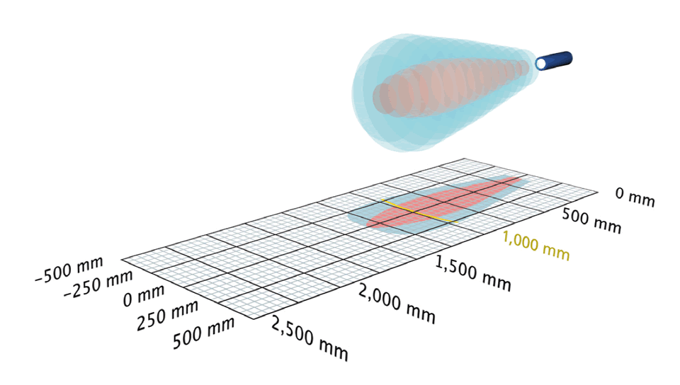
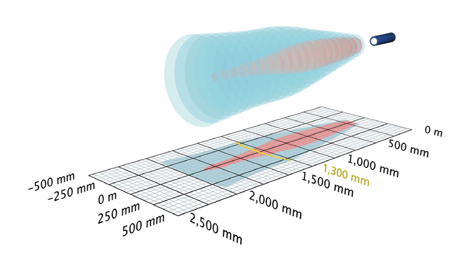
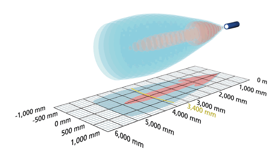
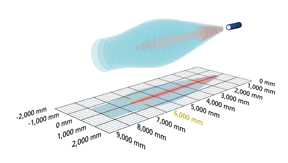
The red areas

are determined with a thin round bar (10 or 27 mm dia. depending on type of sensor) and indicate the typical operating range of a sensor.

In order to obtain the blue areas,

a plate (500 x 500 mm) is introduced into the beam spread from the side. In doing so, the optimum angle between plate and sensor is always employed. This therefore indicates the maximum detection zone of the sensor. It is not possible to evaluate ultrasonic reflections outside the blue beam spread.


A reflector with reflective properties inferior to those of the round bar can be detected in a zone that is smaller than that indicated by the red area. On the other hand, a reflector with better reflective properties will be detected in a zone with a size somewhere between that of the red and blue areas.

A sensor's blind zone determines its smallest permissible detection range. No objects or disturbing reflectors should be placed in the blind zone because this can lead to incorrect measurements.

The operating ranges

given in the diagrams specify the distance at which the ultrasonic sensor can measure common reflectors with sufficient operating reserve. The sensor can also be employed for distances up to its maximum range in the case of good reflectors. The maximum detection range is always greater than the operating range. The diagrams apply for 20 °C, a relative humidity of 50% and normal pressure.

0.07 m  0.7 m 
0.15 m  1.0 m 
0.24 m  1.3 m 
0.25 m  3.4 m 
0.35 m  6.0 m 


These symbols in the technical data show the operating ranges of microsonic ultrasonic sensors.

The attenuation of sound in the air

depends on the temperature and pressure of the air as well as its relative humidity. The physical relationships are complex and have different effects at different ultrasonic frequencies. For simplicity we can say that the attenuation in the air increases with rising temperature and rising humidity. This necessitates a reduction in the size of the detection zones.

With a lower relative humidity and falling temperatures, the attenuation in the air decreases and the detection zones enlarge accordingly.

The reduction in the size of the detection zone is essentially compensated for by the sensor's operating reserves. And at temperatures below 0 °C some sensors can operate over distances certainly twice as large as those given here.

As the pressure of the air rises, so the attenuation in the air drops considerably. This aspect should be taken into account for applications involving overpressure. Sound propagation is impossible in a vacuum.

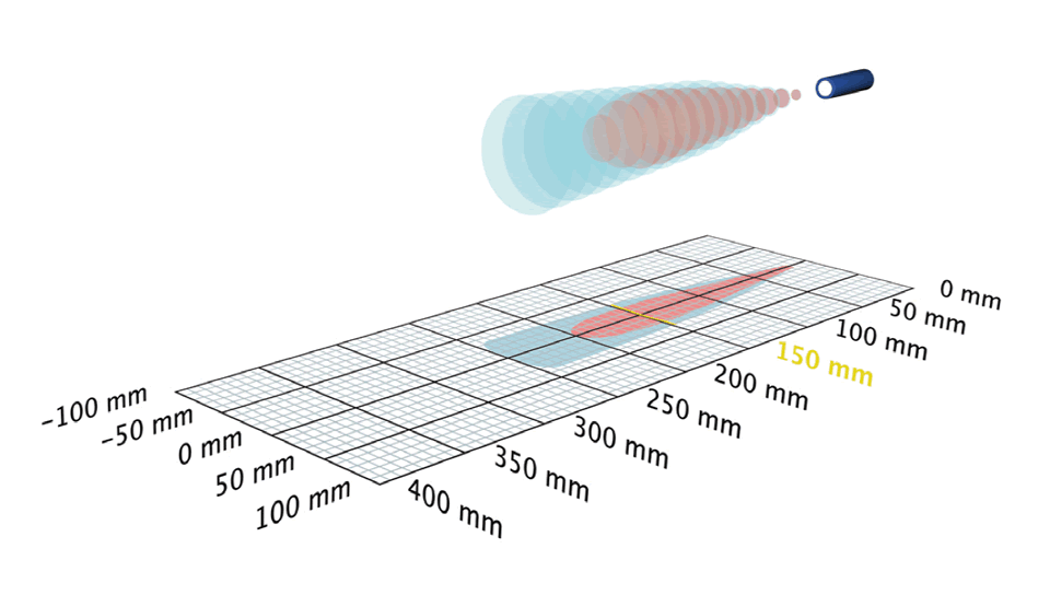
0.15 m

20 mm blind zone
150 mm operating range
250 mm maximum range
f = 380 kHz, λ = 0,9 mm

Used in the following product groups:
 lpc+    nano     nero     pico+     pico+TF     pms     sks     ucs     zws   

Round bar, 10 mm Ø or 27 mm Ø
Operating range
500 x 500 mm plate

0.24 m

50 mm blind zone
240 mm operating range
350 mm maximum range
f = 500 kHz, λ = 0.7 mm

Used in the following product groups:
 nano   ucs    zws  

Round bar, 10 mm Ø or 27 mm Ø
Operating range
500 x 500 mm plate

0.25 m

30 mm blind zone
250 mm operating range
350 mm maximum range
f = 320 kHz, λ = 1.1 mm

Used in the following product groups:
 crm+     hps+      lcs      lpc+      mic      mic+      nero      pico+      pico+TF      pms      wms      zws   

Round bar, 10 mm Ø or 27 mm Ø
Operating range
500 x 500 mm plate

0.35 m

65 mm blind zone
350 mm operating range
600 mm maximum range
f = 400 kHz, λ = 0.9 mm

Used in the following product groups:
 crm+     hps+     lcs     lpc+    mic     mic+     nero     pico+     pico+TF     pms     wms      zws   

Round bar, 10 mm Ø or 27 mm Ø
Operating range
500 x 500 mm plate

0.7 m

120 mm blind zone
700 mm operating range
1,000 mm maximum range
f = 300 kHz, λ = 1.1 mm

Used in the following product groups:
 zws  

Round bar, 10 mm Ø or 27 mm Ø
Operating range
500 x 500 mm plate

1.0 m

120 mm blind zone
1,000 mm operating range
1,300 mm maximum range
f = 200 kHz, λ = 1.7 mm

Used in the following product groups:
 lpc+    nero     pico+    pico+TF     pms   

Round bar, 10 mm Ø or 27 mm Ø
Operating range
500 x 500 mm plate

1.3 m

200 mm blind zone
1,300 mm operating range
2,000 mm maximum range
f = 200 kHz, λ = 1.7 mm

Used in the following product groups:
 crm+     hps+     lcs     mic     mic+     wms 

Round bar, 10 mm Ø or 27 mm Ø
Operating range
500 x 500 mm plate

3.4 m

350 mm blind zone
3,400 mm operating range
5,000 mm maximum range
f = 120 kHz, λ = 2.9 mm

Used in the following product groups:
 crm+     hps+     lcs+     mic     mic+     wms 

Round bar, 10 mm Ø or 27 mm Ø
Operating range
500 x 500 mm plate

6.0 m

600 mm blind zone
6,000 mm operating range
8,000 mm maximum range
f = 80 kHz, λ = 4.3 mm

Used in the following product groups:
 crm+       lcs+     mic     mic+     wms  

Round bar, 10 mm Ø or 27 mm Ø
Operating range
500 x 500 mm plate

Top