mic ultrasonic sensors

Sensor matrix of standard sensors

Overview

These completely metal mic sensors are available in two device designs with five different detection ranges.

download sensor line as pdf

Highlights

  • M30 housing and M12 circular connector in metal design for harsh usage conditions
  • Automatic synchronisation for simultaneous operation of up to ten sensors in close quarters
  • UL Listed to Canadian and US safety standards

Basics

  • 1 switching output in pnp variant
  • Analogue output 4–20 mA and 0–10 V with automatic switching between current and voltage outputs
  • 5 detection ranges with a measurement range of 30 mm to 8 m
  • microsonic Teach-in on pin 5
  • 0.18 mm to 2.4 mm resolution
  • Temperature compensation
  • 9–30 V operating voltage
  • LinkControl for configuration of sensors from a PC

Description

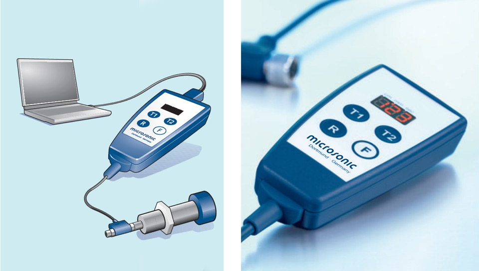
This very solid construction

is fully made of metal from the M30 housing to the M12 circular connector. Since the sensors do not contain any operating elements or signal lamps, they are especially suited for application under extreme ambient conditions with high mechanical loads for housing and plug connector. The sensors are available in five detection ranges and cover a measuring range of 30 mm up to 8 m.

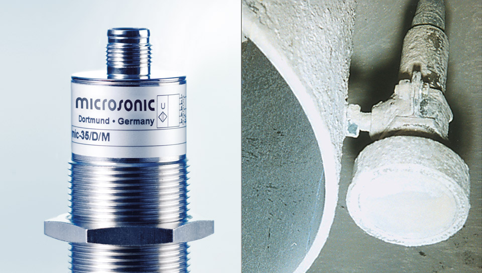
M12 metal circular connector (left) and operation under rough conditions (right)

Two output levels

are available for all five detection ranges:

1 pnp switching output
1 analogue output 4–20 mA and 0–10 V

Sensors with switching output have three operating modes:

  • Single switching point
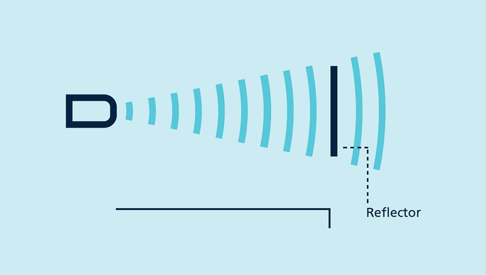
  • Two-way reflective barrier
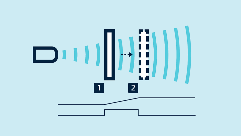
  • Window mode

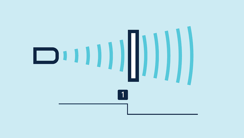
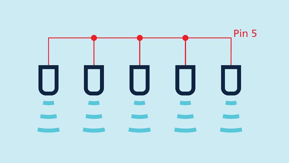
Teach-in of a single switching point

  • Place object to be detected (1) at the desired distance
  • Apply +UB to pin 5 for about 3 seconds
  • Then apply +UB to pin 5 again for about 1 seconds

Teach-in of a switching point

Teach-in of a two-way reflective barrier with a fixed reflector

  • Apply +UB to pin 5 for about 3 seconds
  • Then apply +UB to pin 5 again for about 10 seconds

Teach-in of a two-way reflective barrier

For configuration of a window

  • Place object at the near edge of the window (1)
  • Apply +UB to pin 5 for about 3 seconds
  • Then move the object to the far edge of the window (2)
  • Then apply +UB to pin 5 again for about 1 seconds

Teach-in of an analogue characteristic or a window with two switching points

NCC/NOC 

and rising/falling analogue characteristic curve can also be set via pin 5.

LinkControl

optionally permits the extensive parameterisation of mic sensors. The LCA-2 LinkControl adapter , which is available as an accessory, can be used to connect mic sensors to the PC.

Sensor connected to the PC via LCA-2 for programming

Synchronisation

permits the simultaneous use of multiple mic sensors in an application. To avoid mutual interference, the sensors can be synchronised with one another. To do this, all the sensors are electrically connected on pin 5.

Synchronisation using pin 5

If more than 10 sensors need to be synchronised, this can be carried out with the SyncBox1 , which is available as an accessory.

Top